Hi TotemMaker Team,
I would like to add a smart camera to your robot car chassis. As far as I know, pixy2.1 cameras of charmed labs work with ESP32 in principle.
On a standard ESP32 WROOM board, it connects to MISO, SCK, SS, MOSI, GND.
Is it possible to connect it to RoboBoard X4?
The camera has no wireless connection option like bluetooth or wifi.
Yours,
Birgit
Hello, interesting camera module. Haven’t seen it before. Let’s try to connect with X4!
I see their Arduino library is not intended for use with ESP32, but with simple modification it should work.
- Follow their guide to install library: Hooking up Pixy to a Microcontroller (like an Arduino)
Advanced guide with more details: wiki:v2:porting_guide [Documentation] - Delete Zumo files as mentioned here: Zumo Errors
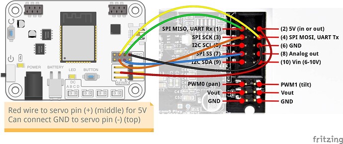
- Connect camera to X4:
Connect Red wire if you want to power camera module from RoboBoard.
NOTE: Older X4 revision v.1.0 board won’t work!
Mapping table of X4 v.1.1 pins:
| Name | Number | SPI | Analog | DAC | Touch |
|---|---|---|---|---|---|
| GPIOA | 14 | MOSI | A0 | - | T0 |
| GPIOB | 23 | MISO | - | - | - |
| GPIOC | 25 | SCK | A2 | DAC2 | - |
| GPIOD | 26 | SS | A3 | DAC3 | - |
Mapping of Pixy2:
- Pin 6 ➜ your controller’s ground signal
- Pin 1 (SPI MISO) ➜ your controller’s SPI MISO signal
- Pin 4 (SPI MOSI) ➜ your controller’s SPI MOSI signal
- Pin 3 (SPI SCK) ➜ your controller’s SPI SCK signal
- Pin 7 (SPI SS) ➜ your controller’s SPI SS signal (if you’re using SPI with SS)
Thank you Arnas, I’ll try that.
Or you can try to use the serial port and save half of GPIO for the future ![]()
Dex is correct. Now he knows thing or two about serial ![]()
SPI is typically used if high transfer speeds are required. For the Pixy library, mostly UART or I2C should be fine. It may by useful with getRGB() function to read video buffer.
Also remember to configure communication method in their software.
To use UART with their library some trickery is required:
#include <Pixy2UART.h> // Use "Pixy2UART" instead of "Pixy2"
Pixy2UART pixy;

int pixy_init() {
  // wait for pixy to be ready -- that is, Pixy takes a second or 2 boot up
  // getVersion is an effective "ping".  We timeout after 5s.
  for(uint32_t t0=millis(); millis()-t0<5000;)
  {
    if (pixy.getVersion()>=0) // successful version get -> pixy is ready
    {
      pixy.getResolution(); // get resolution so we have it
      return PIXY_RESULT_OK;
    }
    delayMicroseconds(5000); // delay for sync
  }
  // timeout
  return PIXY_RESULT_TIMEOUT;
}

void setup()
{
  Serial.begin(115200);
  Serial.print("Starting...\n");

  Serial1.begin(19200, SERIAL_8N1, GPIOA, GPIOB); // Baud 19200 selected
  //  pixy.init(); // Don't call pixy.init()!
  pixy_init(); // Use this function to initialize
}

void loop()
{
  int i;
  // grab blocks!
  pixy.ccc.getBlocks();

  // If there are detect blocks, print them!
  if (pixy.ccc.numBlocks)
  {
    Serial.print("Detected ");
    Serial.println(pixy.ccc.numBlocks);
    for (i=0; i<pixy.ccc.numBlocks; i++)
    {
      Serial.print("  block ");
      Serial.print(i);
      Serial.print(": ");
      pixy.ccc.blocks[i].print();
    }
  }
}
And connect:
- GPIOA → (4) UART Tx
- GPIOB → (1) UART_Rx
To use with I2C:
#include <Pixy2I2C.h> // Use "Pixy2I2C" instead of "Pixy2"
Pixy2I2C pixy;

void setup()
{
  Serial.begin(115200);
  Serial.print("Starting...\n");
  Wire.setPins(GPIOA, GPIOB); // Set I2C pins to SDA: GPIOA, SCL: GPIOB
  pixy.init();
}

void loop()
{
  int i;
  // grab blocks!
  pixy.ccc.getBlocks();

  // If there are detect blocks, print them!
  if (pixy.ccc.numBlocks)
  {
    Serial.print("Detected ");
    Serial.println(pixy.ccc.numBlocks);
    for (i=0; i<pixy.ccc.numBlocks; i++)
    {
      Serial.print("  block ");
      Serial.print(i);
      Serial.print(": ");
      pixy.ccc.blocks[i].print();
    }
  }
}
And connect:
- GPIOA → I2C SDA (9)
- GPIOB → I2C SCL (5)
